
Test Stand Designer & Builder, | Team “Venom Tires” (with Max Ma, Clayton Nehls, Casey Nguyen) | UW–Madison Senior Design | Fall 2025 – Spring 2026
The Problem
Tires force a tradeoff. An aggressive off-road tread gives grip on loose terrain but wastes energy and adds noise on pavement; a smooth road tire is efficient and quiet but useless off-road. Today the only real solutions are compromising with an all-terrain tread or owning, and swapping between, two full sets of tires.
Our Solution
Our team designed a 3D-printed tire whose tread pattern physically changes shape, from an aggressive off-road profile to a smooth slick, by modulating internal air pressure. Individual tread blocks sit on small inflatable bladders: pressurize them and the blocks rise into an low-profile, efficient road tread; deflate them and the blocks retract into showing just the stationary off-road tread.
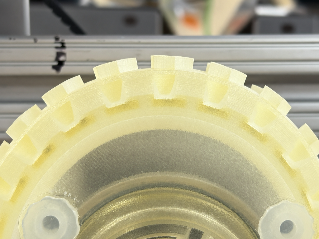
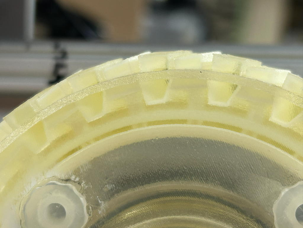
Close-up of the same tread section deflated (left) vs. inflated (right) — the blocks visibly raise as pressure increases.
We validated the concept against real automotive test standards (ISO 28580 for rolling resistance, UN/ECE R117 for grip and noise, ASTM F1805 for traction, SAE J2657 for pressure monitoring) and against four stakeholder groups — a client wanting a testable prototype, recreational users wanting one tire instead of two, emergency/military users needing all-terrain reliability, and autonomous vehicles needing pressure changes with zero human input.
Material Selection & Simulation
The tread blocks needed a flexible material that could survive repeated inflation cycles without tearing, while the wheel hub needed a rigid, structural material. We ran uniaxial stress-strain data for a range of hyperelastic candidates (50A–95A durometer) and rigid candidates through Ansys, fitting a Mooney-Rivlin 3-parameter hyperelastic model to predict how each 3D-printed resin would actually behave before committing to a print.
Testing Methods
We defined four key metrics — rolling resistance, slip, noise, and drawbar pull — and built a dedicated drum test stand (my primary contribution, detailed below) to measure them cheaply and repeatably without needing a full vehicle or a real road surface.
Building the Tire Prototype
Early iterations used FEA to check that the tread blocks wouldn’t over-deform or fail at their attachment points under load, then moved to single-block “test section” prototypes — a single 3D-printed flexible tread wedge with its own inflation line — before scaling up to a fully assembled wheel with every tread block installed and a central valve for inflation control.
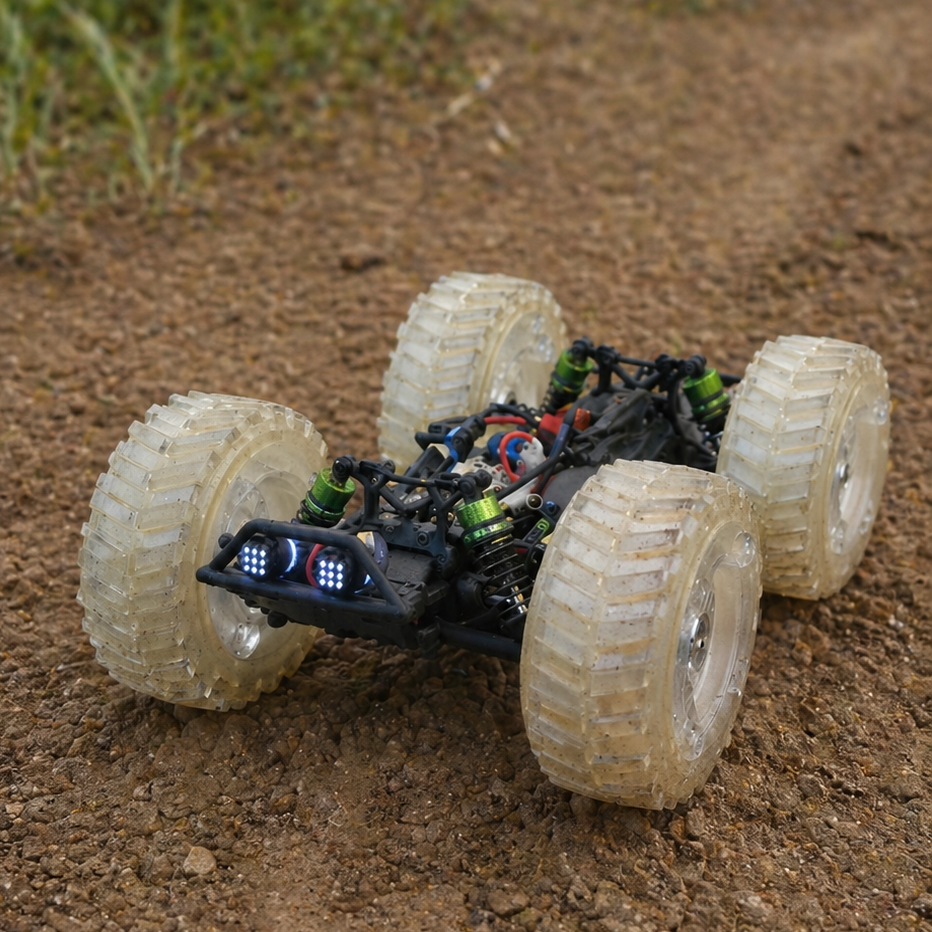
The finished tire design mounted on our RC-scale test vehicle
Designing & Building the Test Stand
This was my main contribution to the project: a complete drum-type friction dynamometer, designed from scratch to characterize the tire across both tread states.
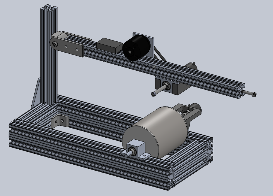
Mechanical design: The stand pivots the tire, mounted on an arm on an 8020 pivot joint, down onto a rotating 6″ OD steel drum that stands in for a road surface, with a weight horn to set the normal load. A 6374 brushless motor and 70A ESC drive the drum, while a pair of quadrature encoders (one on the tire axle, one on the drum axle) independently measure how fast each is spinning, which is what lets us calculate wheel slip.
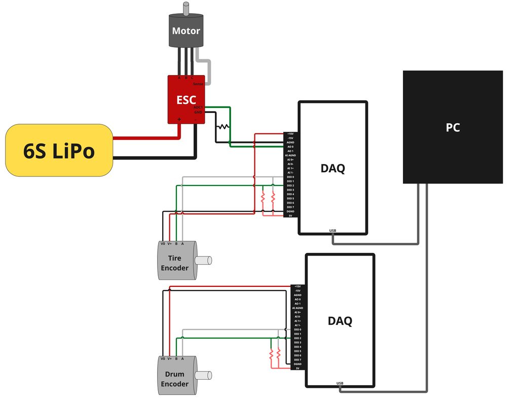
Electrical design: I wired the full system – a 6S LiPo powering the motor through the ESC, with the ESC’s current-sense line and both encoders feeding into two DAQ units that log everything back to a PC over USB.
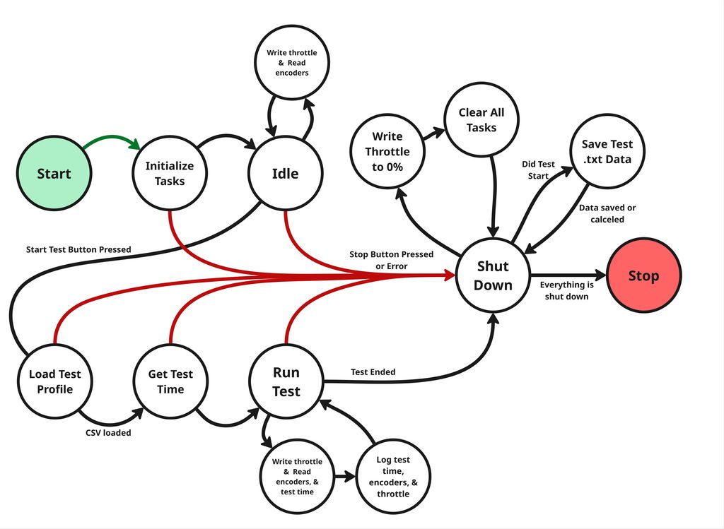
Controls: I wrote the LabVIEW control software as a state machine so tests are safe and repeatable. It loads a test profile from a CSV, runs the programmed throttle sequence while logging throttle, tire speed, drum speed, and time, and can drop into a dedicated Shut Down state from any active state the moment the stop button is pressed or an error occurs, so the drum and motor always come to a safe stop.
Results
Rolling Resistance. Using the ESC’s built-in current sensing to measure test power against a measured parasitic baseline, the inflated (slick) tire showed a lower coefficient of rolling resistance (0.0108 ± 0.0014) than the deflated (off-road) tire (0.0138 ± 0.0014) — the smooth mode rolls more efficiently, as expected.
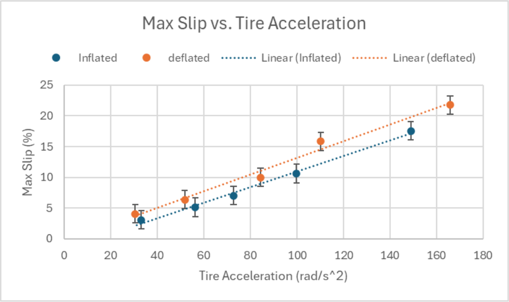
Noise. At a fixed drum speed of 670 RPM, the inflated tire measured 86 dB versus 92 dB for the deflated tire and 93 dB for a stock RC tire baseline (±2 dB) — the smooth mode is noticeably quieter.
Where This Adds Value
Looking past the prototype, the strongest use cases we identified were emergency/service vehicles (no time to swap tires on unpredictable terrain), recreational vehicles (one tire system instead of two full sets), and autonomous/robotic vehicles (pressure-based adaptation with zero human intervention). A rough payback analysis put the break-even cost for an adaptive tire system at roughly $2,400–$3,100+ for consumer and emergency use cases, and as low as $300–$700+ for small robotic platforms.